DIGITAL SELECTOR SWITCHES
CAMÉ S6000 / S7000

Built-in (S6000) or external (S7000), digital selector switch, burglar-proof, 7-digit keyboards

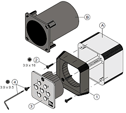
Keys to Diagram:
A) External housing
B) Built-in housing
1) Front frame
2) Frame fixing screws
3) Keyswitch unit
4) Screw and key for unit
TECHNICAL SPECIFICATIONS
| Voltage | Current Draw | Power consumption (1) | Personal code digits |
Number of combinations |
Operating temperature range |
Degree of pretection |
| 12V ac/dc | 22 mA | 0.3 W | 6 max. | 1,679,676 max. |
- 20°C / +70°C | IP 54 |
| 24V ac/dc | 70 mA | 1.7 W | ||||
| (1) Values are approximate when unit is in idle mode, with increments of ~50 mA for every exit activated | ||||||
ASSEMBLY:
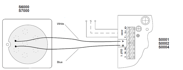
Have the wiring from the control card reach the point where the selector switch is mounted:
Use screw anchors to mount the wall-mounted selector switch housing (A) on the wall, or install the built-in housing (B) in the wall, inserting the electric wiring in the casing itself (making use of the marked holes):
-
Affix the front frame (1);
-
Make the necessary power connections;
-
Insert the switch unit (3) and fasten it to the frame.


