ACCESS CONTROL DEVICES - CAME ZA3
Description of control board
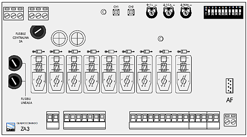
The ZA3 electric board is suitable for controlling the automation of ATI, FERNI and FROG series 230V swing gates with up to 600W power and 50- 60Hz frequency.
Wholly designed and built by CAME S.p.A., it meets UNI 8612 regulations in force. The board is inserted and fixed to the ABS case (S4339 o S4340), which has an IP54 protection level, with air recycling inlet and transformer.
The board requires 230V (a.c.) at terminal blocks L1-L2 and the inlet is protected with two 5A fuses. A 3.15A fuse protects the low voltage command devices.
The accessories’ total wattage (24V) must not exceed 20W.
Safety
Photocells can be connected to obtain: - Re-opening during closure (2-C1), if the photocells identify an obstacle while the gate is closing, they will reverse the direction of movement until the gate is completely open; - Re-closing during opening (2-CX, dip 8OFF-10OFF), if the photocells identify an obstacle while the gate is opening, they will reverse the direction of movement until the gate is completely closed; - Partial stop, shutdown of moving gate, with activation of an automatic closing cycle (2-CX); - Total stop (1-2), shutdown of gate movement without automatic closing; a pushbutton or radio remote control must be actuated to resume movement).
NB: If an NC safety contact (2-C1, 2- CX, 1-2) is opened, the LED will flash to indicate this fact.
Accessories which can be connected to this unit:
-
"Gate open" signal light (10-5);
-
Cycle lamp - The lamp which lights the manoeuvring zone: it remains lit from the moment the doors begin to open until they are completely closed (including the time required for the automatic closure). In case automatic closure is not enabled, the lamp remains lit only during movement (EE3);
-
Electric lock (11-S).
Other functions available
-
Automatic closing: The automatic closing timer is automatically activated at the end of the opening cycle. The preset, adjustable automatic closing time is automatically interrupted by the activation of any safety system, and is deactivated after a STOP command or in case of power failure;
-
Obstacle presence detection: When the motor is stopped (gate is closed, open or half-open after an emergency stop command), the transmitter and the control pushbutton will be deactivated if an obstacle is detected by one of the safety devices (for example, the photocells);
-
Hammer movemen:. At every opening command, the wings press the closing stop-ledge for a second, thus facilitating the release operation of the electric lock connected to terminals 11-S. It is only active if the wings are closed and at the end of the work time or at the 1st manoeuvre after the system has been powered;
-
Enabling functions of partial stop or re-closure during opening, normallyclosed contact (2-CX), select one of the two functions by setting Dip switch (see below);
-
"Operator present" function: Gate operates only when the pushbutton is held down (the radio remote control system is deactivated);
-
Partial opening, second motor door opening, adjusted with TR2M trimmer; it is activated by collecting to the terminals 2-3P;
-
Pre-flashing for 5 seconds, while the door is opening and closing;
-
Type of command: -open-stop-close-stop for pushbutton and radio transmitter; -open-close-reverse for pushbutton and radio transmitter; -open only for radio transmitter.
Adjustments
- Automatic closure time;
- Partial opening time and delay in closing of the M2 motor;
- Operating time.
![]() Important! Disconnect the unit from the main power lines before carrying out any operation inside the unit.
Important! Disconnect the unit from the main power lines before carrying out any operation inside the unit.
10 way Dip Switch

1 ON Automatic closure enabled; (1 OFF-disabled)
2 ON "Open-stop-close-stop" with button (2-7) and radio control (AF board inserted) enabled;
2 OFF "Open-close" with button (2-7) and radio control (AF board inserted) enabled;
3 ON "Only opening" with radio control (AF board inserted) enabled; (3 OFF-disabled)
4 ON Pre-flashing (opening and closing) enabled; (4 OFF-disabled)
5 ON Obstacle detection device enabled; (5 OFF - disabled)
6 OFF "Operator present" (radio remote control is deactivated when function is selected) disabled; (6 ON - enabled)
7 ON Hammer movement operation enabled; (this function helps unlock the electric lock) (7 OFF - disabled)
8 OFF - 10 OFF Re-closure during opening (connect the safety device on terminals (2-CX) enabled;
8 OFF - 10 ON Partial stop (connect the safety device on terminals (2-CX) enabled; (if the devices on the 2-CX terminals are not used, set Dip 8 in ON)
9 OFF Re-opening in closing phase (connect the safety device on terminals 2-C1) enabled; if not used, set the dip-switch to ON.


