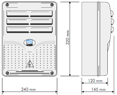
ACCESS CONTROL DEVICES - CAME ZL19
Description of control panel
Control panel for 24V d.c. gear motors, powered by 230V a.c. at 50-60 Hz (singlephase). Designed to control ATI, FERNI and FROG gear motors.
Designed and built entirely by CAME CANCELLI AUTOMATICI S.p.A. to meet UNI 8612 safety standards at an IP 54 level of protection.
Housing in ABS is equipped with vents to provide internal air circulation. Guaranteed 12 months, unless tampered with. This control panel is powered by 230V a.c. across terminals L1 and L2, and is protected by a 3.15A fuse on the main power line. Control systems are powered by low voltage and protected by a 630mA fuse.
The total power consumption of 24V accessories (which are protected by a 3.15A fuse) must not exceed 40 W.
Safety
Photocells can be connected to obtain: -
-
Re-opening during the closing cycle (2- C1), if the photocells identify an obstacle while the gate is closing, they will reverse the direction of movement until the gate is completely open;
-
Partial stop, shutdown of moving gate, with activation of an automatic closing cycle (2-C3);
-
Total stop (1-2), shutdown of gate movement without automatic closing; a pushbutton or radio remote control must be actuated to resume movement).
-
Safety test function. The control unit will now check the safety system every time an opening or closing command is given (see p. 26).
-
The electrical panel includes an amperometric sensor for the motors which is triggered whenever an obstacle blocks movement during opening or closing. If operating speed, the sensor inverts the movement direction. If it is slowing down, one motor stops while the other completes its movement.
-
The sensor's sensitivity can be adjusted using the trimmers (see p.12).
-
The transformers are equipped with a guard, which in case of thermal overload will keep the doors open. They are closed again only after the temperature falls below the emergency threshold.
Accessories which can be connected to this unit:
-
“Gate open” signal light;
-
Flashing signal light when gate is in motion;
-
Electric lock;
-
LB18 circuit card for emergency battery, which is automatically connected in case of power failure; battery is recharged when line power is restored;
-
Radiofrequency AF board (see table page 29).
Other functions available:
-
Automatic closing: The automatic closing timer is automatically activated at the end of the opening cycle. The preset, adjustable automatic closing time is automatically interrupted by the activation of any safety system, and is deactivated after a STOP command or in case of power failure;
-
Obstacle detection: When the motor is stopped (gate is closed, open or half-open after an emergency stop command), the transmitter and the control pushbutton will be deactivated if an obstacle is detected by one of the safety devices (for example, the photocells);
-
Hammer movement: This feature makes it easy for the lock to release (the door wings momentarily press against the closure stops when the open command is given, which facilitates release of the electric lock);
-
Cycle lamp: The lamp which lights the manoeuvring zone: it remains lit from the moment the doors begin to open until they are completely closed (including the time required for the automatic closure). In case automatic closure is not enabled, the lamp remains lit only during movement (10-E3). Select it using the jumpers (see p. 20);
-
The panel is enabled at the command for ATI gearmotors or at the command for FERNI and FROG gearmotors, which can be selected with the 4-way dip-switch (see p. 23).
-
"Operator present" function: Gate operates only when the pushbutton is held down (the radio remote control system is deactivated);
-
Flashing light activated before opening and closing cycle begins;
-
Type of command:
- «open-stop-close-stop» for pushbutton and radio transmitter;
- «open-close-reverse» for pushbutton and radio transmitter;
- «open only» for radio transmitter.
Adjustments:
-
REG/FINE trimmer = Fine adjustment of amperometric sensitivity during motor operation;
-
Trimmer SENS/VEL = Adjustment of amperometric sensitivity during operating: min/max;
-
Trimmer SENS/RALL = Adjustment of amperometric sensitivity during slowdown: min/max;
-
Trimmer TCA = Adjustment of automatic closing time: 2" to 120";
-
Trimmer TR2M = Delay on closing cycle - motor 2: 1" to 15";
-
Trimmer TL = Adjustment of operating time: 13" to 120";
-
Faston connectors on the circuit card are used to select normal operating and slowdown speeds;
![]() Caution! Shut off the mains powerand disconnect the batteries beforeservicing the inside of the unit.
Caution! Shut off the mains powerand disconnect the batteries beforeservicing the inside of the unit.
MOTHERBOARD
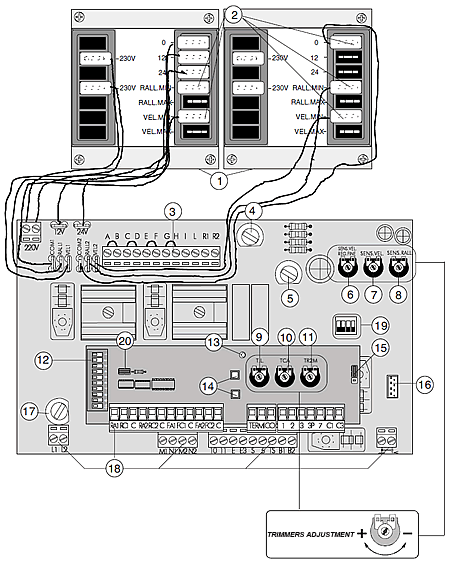
COMPONENTS
-
Transformer
-
Connectors for speed selection
-
Terminal board for connectiong battery charger LB18 (connect a bridge across terminals A-B; C-D; E-F; G-H if battery
charger is not used) -
Fuse on accessory power line, 3.15A
-
Fuse on central control unit, 630 mA
-
Fine adjustment of amperometric sensitivity during motor operation
-
Trimmer for adjustment of amperometric sensitivity during operation
-
Trimmer for adjustment ofamperometric sensitivity during slowdown
-
Trimmer for adjustment of operating time
-
Trimmer for adjustment of automatic closing
-
Trimmer for adjustment of delay on closing cycle motor n.2
-
10-dip function switch (see pag.24)
-
Radio code/automatic closing signal LED
-
Button for memorizing code numbers
-
Jumper which selects output B1-B2/ operating cycle indicador light
-
Radiofrequency board socket
-
Line fuse, 3.15A
-
Terminal block for external conections
-
4-dip function switch (see pag.23)
-
Jumper for selection of type of controlfor button in 2-7
NOTE: For more details about Electrical Connections etc, please download the pdf brochure which has these details in several languages
