


FAAC MODEL 400 HYDRAULIC SWING GATE OPERATOR

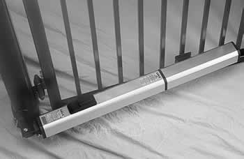
The Model 400 is specifically designed for situations needing maximum versatility, such as apartment, subdivision, commercial / industrial and residential applications. It’s strength also makes the 400 ideal for large ornate gates.
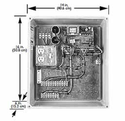
Model 400 operators are controlled by the 450 MPS Control Panel.
-
One 450 MPS operates single leaf or bi-parting gates
-
Choice of 6 operating modes including:
- "pulse-to-open, pulse-to-close"
- automatic timed closure, including NEW HOLD OPEN function
- "man present" (separate open and close contacts) -
Easy interconnection of loop detectors, photocells, etc. to reverse a gate if an obstacle is sensed
-
Easy interconnection of actuating devices like remote control radios, key pads and telephone entry systems
-
On-board diagnostic LEDs
-
Concealed positive gate stops available
| Parameter |
Model 400 Standard | Model 400 Rapid | Model 400 Large Leaf | Model 400 Extended Geometry |
| Application | Certain apartment, subdivision, commercial, industrial, residential single leaf or bi-parting gate (vehicles only, not for pedestrian use) |
|||
| Cycles per hour | ||||
| Maximum gate swing | 115 degrees | 115 degrees | 115 degrees | 125 degrees |
| 90 degree opening time |
17 seconds | 12 seconds | 23 seconds | 17 seconds |
| Maximum weight | 1300 pounds | 900 pounds | 2000 pounds | 1300 pounds |
| Maximum length per gate leaf | 18 feet (5.5 m) | 12 feet (3.7 m) | 23 feet (7 m) | 18 feet (5.5 m) |
| Approx. operating temperature range | -33°F to 165°F (-36°C to 74°C) (For extreme temperature conditions, arctic grade fluid is available upon request) |
|||
| Hydraulic locking | Available in opened and/or closed positions |
Available in opened and/or closed positions | Not available | Available in opened and/or closed positions |
| Voltage | 115 VAC (2.5 A) or 230 VAC (1.5 A) | |||
| Note: Operator specifications are approximate. Environmental factors can change the performance of the operator. Your installer will advise you which model of operator will work best for your site and application. | ||||
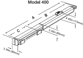
| STANDARD | Extended Geometry (EG) | |
| A | 40.5 in (102.87 mm) | 50.5 in (128.87 mm) |
| B | 27.5 in (69.85 mm) | 32.38 in (82.25 mm) |
| C | 10.25 in (26.04 mm) | 15 in (38.1 mm) |

Mounting dimensions for OUTWARD-swinging
400 operators, top view

Dimensions
A 5 in. (13 cm)
B 5 in. (13 cm)
C 27.56 in. (70 cm)
D no limit
E MUST be less than A
Mounting dimensions for INWARD-swinging
400 operators, top view

| Model | 90° Swing | 115° Swing | 125° Swing | |
| 400 Standard, high speed and slow speed models |
A | 5 in. (13 cm) | 4 in. (10 cm) | N/A |
| B | 5 in. (13 cm) | 4.75 in. (12 cm) | N/A | |
| C | 38.19 in. (97 cm) | 38.19 in. (97 cm) | N/A | |
| D | max. 3 in. (8 cm) | max. 2 in. (5 cm) | N/A | |
| 400 EG (Extended Geometry) |
A | 7.88 in. (20 cm)* or 11.5 in. (29 cm)** | 5.75 in. (14.6 cm)** | 4.75 in. (12 cm) |
| B | 7.5 in. (19 cm)* or 3 in. (7.5 cm)** | 7 in. (17.8 cm) | 6.63 in. (17 cm) | |
| C | 47.63 in. (121 cm) | 47.5 in. (120 cm) | 47.5 in. (120 cm) | |
| D | up to 5.25 in. (14 cm)* or 10 in. (25.5 cm)** | up to 3.5 in. (8.9 cm)** | up to 2.88 in. (7 cm) | |
| * For A, B, and D, if you choose one of these values with one asterisk, then you must choose the other values with one asterisk. ** For A, B, and D, if you choose one of these values with two asterisk, then you must choose the other values with two asterisks. |
||||